Overview
This is a guide on how to use the camera calibration repository[email protected]:GenRobo/camera_calibration.git to do an extrinsic camera calibration for robot arms.
Step 1: Create a Calibration Target
Generate a Radon Checkerboard pattern using thegen_pattern.py script. For example:
- There is a white border of at least one square-width on all sides of the pattern
- The pattern is unobscured and has no creases or unevenness
- Measure the square side-lengths to make sure they are to scale
Step 2: Calibrate the Camera
You will have to write a script that provides all of the necessary information to theextrinsic_calibration_interactive() function. The examples/ directory shows how to do this in various configurations of robots and cameras. These examples automatically run interactive data collection and calibration:
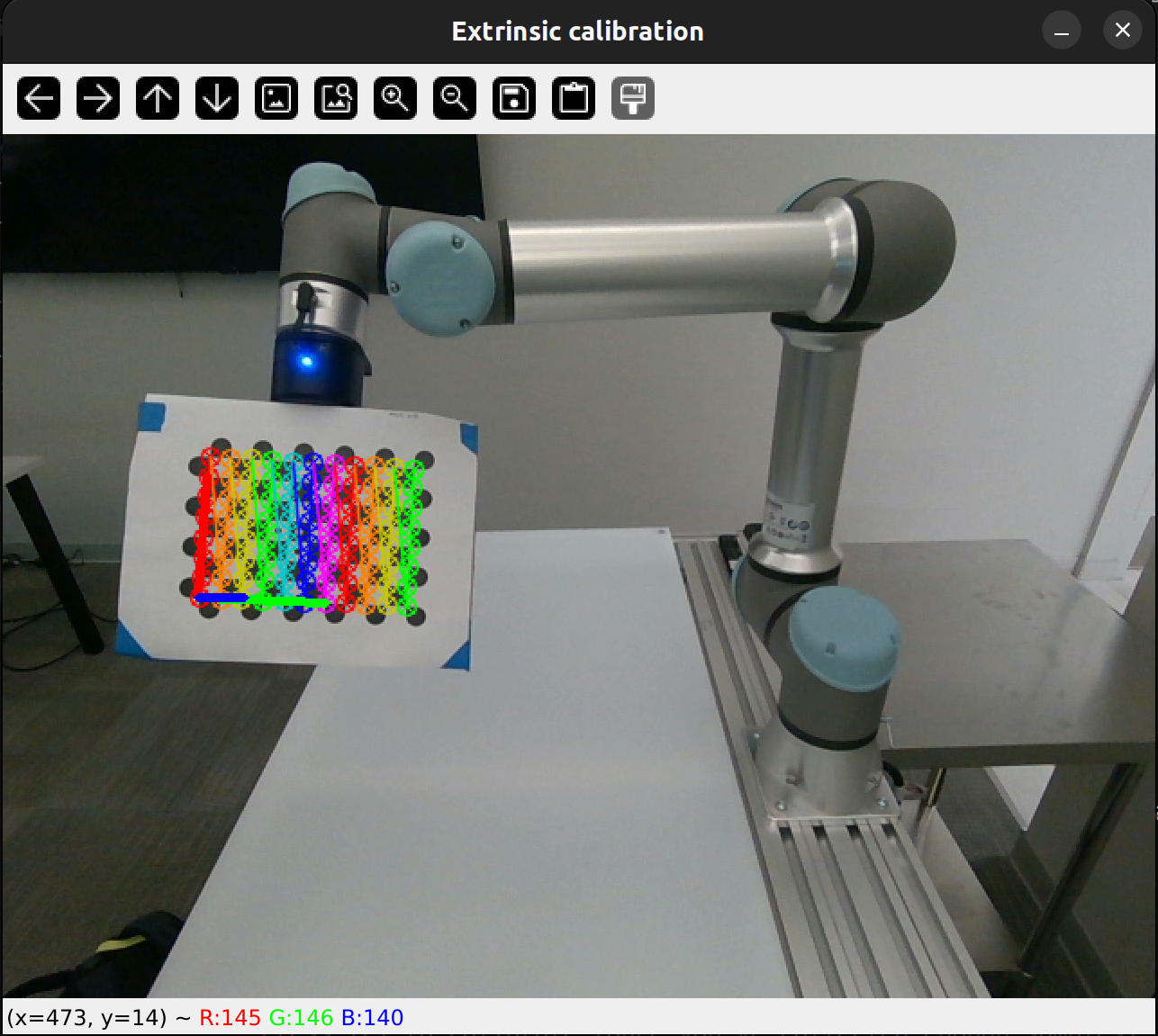
Data collection: When you start the script, a video feed will be shown with the detected calibration target. You need to free-drive the robot to different positions and orientations. Press [Spacebar] to collect a sample and [c] to move on to calibration (once you have collected enough samples).
Each “sample” consists of the robot’s end-effector pose (from inverse kinematics) and the detected points of the calibration target in the camera’s image. For a good calibration, you need to get a good distribution of size, skew, and location of the calibration target in the image. 10-15 samples generally gives good results, but more is better.
You should expect to see the following display and terminal output:
FAQ: The calibration target does not appear to be recognized in the image. Answer: Make sure that the target is non-reflective and has the correct number of rows and columns. This script counts the number of squares in the row and column count, but openCV convention is sometimes to take the number of interior corners (the number of points detected in the image), which is one less than the number of squares.Calibration: Once enough samples are collected, you can press [c] to calibrate the camera. Internally this uses the OpenCV function
calibrateHandEye.
The output will be a csv file containing the camera’s pose with respect to the desired robot link. For a Hand-in-Eye calibration this will be camera_wrt_base.csv, and for Eye-in-hand calibration this will be camera_wrt_gripper.csv (where ‘wrt’ means “with respect to”).
You will also get a reprojection error, which tells you the pixelwise distance between the actual detected points, and the reprojection of the 3D pattern points using the transforms output by the calibration. As a rule of thumb, a “good” calibration will have a reprojection error of less than 0.15 pixels, and if the error is over 0.3 then you should re-do the calibration.
Step 3: Visualize the Results
Thevisualize_calibration.py file also contains functions that can be used to visualize the camera’s pose and end-effector pose relative to the robot base. Examples are shown in the examples/ directory. The plot is simple, but it can show movements of the end-effector in real time.
Tested with:
Robots:- UR5e
- WidowX 250S
- Realsense D435i
- Realsense D455
- Zed 2i