> ## Documentation Index
> Fetch the complete documentation index at: https://docs.generalrobotics.dev/llms.txt
> Use this file to discover all available pages before exploring further.
# Camera
For both aerial and wheeled robots, AirGen offers a comprehensive suite of camera sensors that play a crucial role in simulation and data generation. These sensors provide various modalities representative of commonly used sensor types and are essential for creating high-fidelity data for AI model training or testing.
## Camera Modalities
AirGen has several classes of camera modalities, offering unique data essential for different aspects of robotic perception and navigation. Below is a list of modalities that are available:
* **RGB**: The most commonly used camera sensor: captures RGB/scene data.
* **Depth**: Capture depth information to understand the spatial structure of the environment.
* **Segmentation**: Provide segmented views of the scene, useful for object recognition and scene understanding.
* **Infrared**: Capture thermal data, enhancing vision in low-light conditions.
* **Surface Normals**: Provide data on surface orientation, critical for detailed object understanding.
* **Optical Flow**: Track motion across frames, aiding in dynamic scene analysis.
### Available Camera Modalities
Each camera modality is identified by an `ImageType` integer. The table below lists the current camera sensor modalities available in AirGen:
| Camera Type | ImageType |
| ----------------------- | --------- |
| **Scene (RGB)** | 0 |
| **DepthPlanar** | 1 |
| **DepthPerspective** | 2 |
| **DepthVis** | 3 |
| **DisparityNormalized** | 4 |
| **Segmentation** | 5 |
| **SurfaceNormals** | 6 |
| **Infrared** | 7 |
| **OpticalFlow** | 8 |
| **OpticalFlowVis** | 9 |
### Camera Placement and Configuration
AirGen robots typically feature five strategically placed cameras: `front_center`, `front_right`, `front_left`, `bottom_center`, and `back_center`. These positions ensure comprehensive coverage for simulation scenarios. The desired camera can be targeted by specifically stating the string from the ones listed above.
## Image Capture
### Extracting and Visualizing an RGB Image
Rendering an image through any of these cameras involves two steps:
1. Use the `getImages` API: Use the getImages API to retrieve images from the desired camera, specifying the types of images (e.g., RGB, Depth). This API returns a list of images along with their associated camera poses.
For example, to retrieve RGB and Depth perspective images from the front center camera (assuming the AirGen client has been set up):
```python theme={null}
# Retrieve both Scene (RGB) and Depth images from the front center camera
image_data = client.getImages(
"front_center",
[airgen.ImageType.Scene, airgen.ImageType.DepthPerspective]
)
```
The image\_data is a list of tuples where each tuple contains an image and the corresponding camera pose at the time the image was captured.
2. Parse the Response and Extract Images: The image\_data list contains multiple entries based on the requested image types. Each entry consists of the actual image and the camera pose at the time of capture.
Extracting and Visualizing the RGB Image:
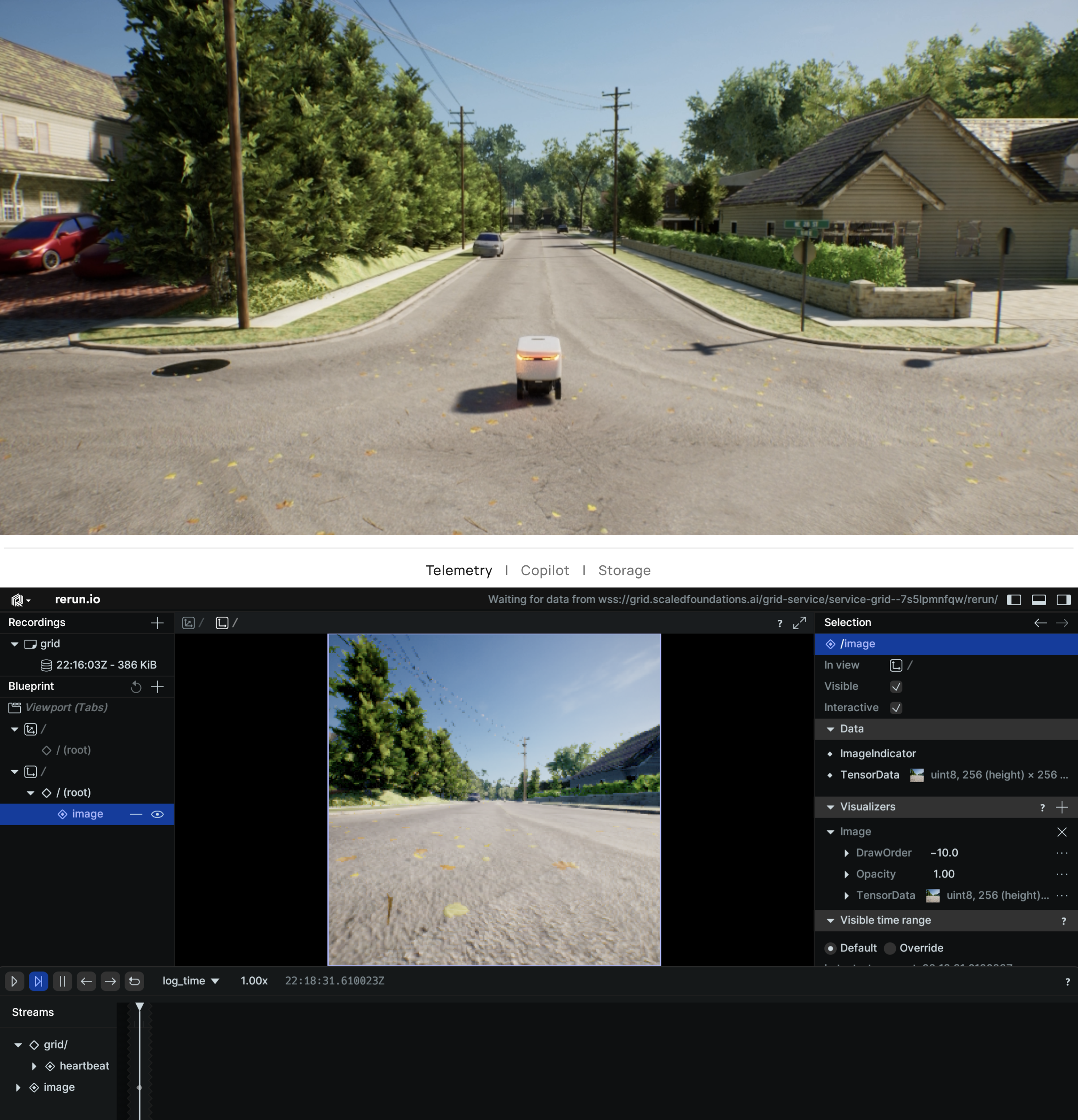
You can extract the first image (RGB) and visualize it using the rerun library as follows:
```python theme={null}
# Extract the first image, which is the RGB image, and the camera's pose
rgb_image, camera_pose = image_data[0]
# Visualize the RGB image using Rerun
import rerun as rr
rr.log("image", rr.Image(rgb_image))
```
 AirGen returns the images in RGB ordering, but OpenCV uses BGR ordering. So, you may need to reverse the channel order if you wish to use these images with OpenCV.
### Extracting and Visualizing a Depth Image:
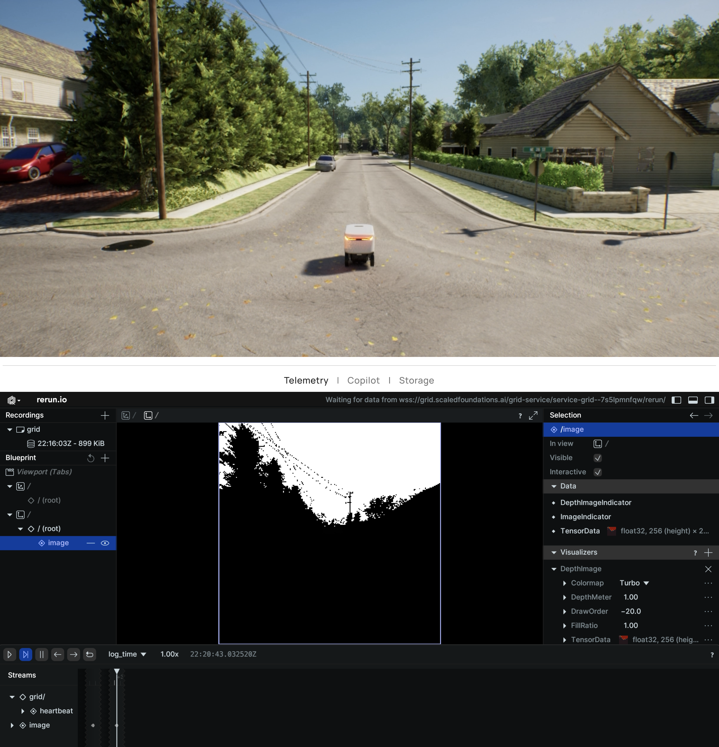
Similarly, you can extract and visualize the depth image using the `rerun.DepthImage` wrapper:
```python theme={null}
# Extract the second image, which is the Depth image, and the camera's pose
depth_image, camera_pose = image_data[1]
# Visualize the Depth image using Rerun
import rerun as rr
rr.log("image", rr.DepthImage(depth_image))
```
AirGen returns the images in RGB ordering, but OpenCV uses BGR ordering. So, you may need to reverse the channel order if you wish to use these images with OpenCV.
### Extracting and Visualizing a Depth Image:
Similarly, you can extract and visualize the depth image using the `rerun.DepthImage` wrapper:
```python theme={null}
# Extract the second image, which is the Depth image, and the camera's pose
depth_image, camera_pose = image_data[1]
# Visualize the Depth image using Rerun
import rerun as rr
rr.log("image", rr.DepthImage(depth_image))
```
 ## Camera Control
AirGen provides methods for controlling camera settings within the simulation environment, including camera pose and field of view (FOV). Below are the key methods for camera manipulation.
### simSetCameraPose
***
This function sets the pose (position and orientation) of a specified camera. You can control both internal and external cameras.
```python theme={null}
def simSetCameraPose(self, camera_name, pose, robot_name="", external=False):
"""
Set the pose of a camera.
Args:
camera_name (str): Name of the camera
pose (Pose): Desired position and orientation
robot_name (str, optional): Associated robot name
external (bool, optional): Controls an external camera
"""
self.client.call("simSetCameraPose", str(camera_name), pose, robot_name, external)
```
**Example:**
To set the pose of the `front_center` camera using AirGenCar:
```python theme={null}
import airgen
import time
import math
from grid.robot.airgen_car import AirGenCar
airgen_car_0 = AirGenCar()
client = airgen_car_0.client
def euler_to_quaternion(pitch, roll, yaw):
# Convert Euler angles to quaternion
pitch, roll, yaw = map(math.radians, [pitch, roll, yaw])
cy, sy = math.cos(yaw * 0.5), math.sin(yaw * 0.5)
cr, sr = math.cos(roll * 0.5), math.sin(roll * 0.5)
cp, sp = math.cos(pitch * 0.5), math.sin(pitch * 0.5)
return airgen.Quaternionr(cy * cr * cp + sy * sr * sp, cy * sr * cp - sy * cr * sp, cy * cr * sp + sy * sr * cp, sy * cr * cp - cy * sr * sp)
initial_pose = client.simGetCameraInfo("front_center").pose
test_poses = [
airgen.Pose(airgen.Vector3r(0, 0, -10), euler_to_quaternion(0, 0, 0)),
airgen.Pose(airgen.Vector3r(0, 0, -10), euler_to_quaternion(0, 0, 90)),
]
for pose in test_poses:
client.simSetCameraPose("front_center", pose)
time.sleep(2)
client.simSetCameraPose("front_center", initial_pose)
```
**Arguments:**
* **camera\_name:** Name of the camera
* **pose:** Pose object representing position and orientation
* **robot\_name:** (Optional) Robot to which the camera is attached
* **external:** (Optional) Controls external cameras
**Notes:**
* The Pose object follows the North-East-Down (NED) coordinate system.
* This method supports external camera control using the external flag.
### simSetCameraFov
Modifies the field of view (FOV) of a selected camera.
```python theme={null}
def simSetCameraFov(self, camera_name, fov_degrees, robot_name="", external=False):
"""
Set the FOV of a camera.
Args:
camera_name (str): Name of the camera
fov_degrees (float): FOV in degrees
robot_name (str, optional): Associated robot name
external (bool, optional): Controls an external camera
"""
self.client.call("simSetCameraFov", str(camera_name), fov_degrees, robot_name, external)
```
**Example:**
Set the FOV for the `front_center` camera to 90 degrees:
```python theme={null}
client.simSetCameraFov("front_center", 90.0)
```
**Arguments:**
* **camera\_name:** Name of the camera
* **fov\_degrees:** FOV in degrees
* **robot\_name:** (Optional) Associated robot name
* **external:** (Optional) Controls external cameras
### Coordinate System and Frame of Reference
Camera position and orientation follow the North-East-Down (NED) frame:
* **X:** Points forward (north)
* **Y:** Points right (east)
* **Z:** Points downward
Please ensure your poses are aligned with this frame.
## Further Reading
### Depth
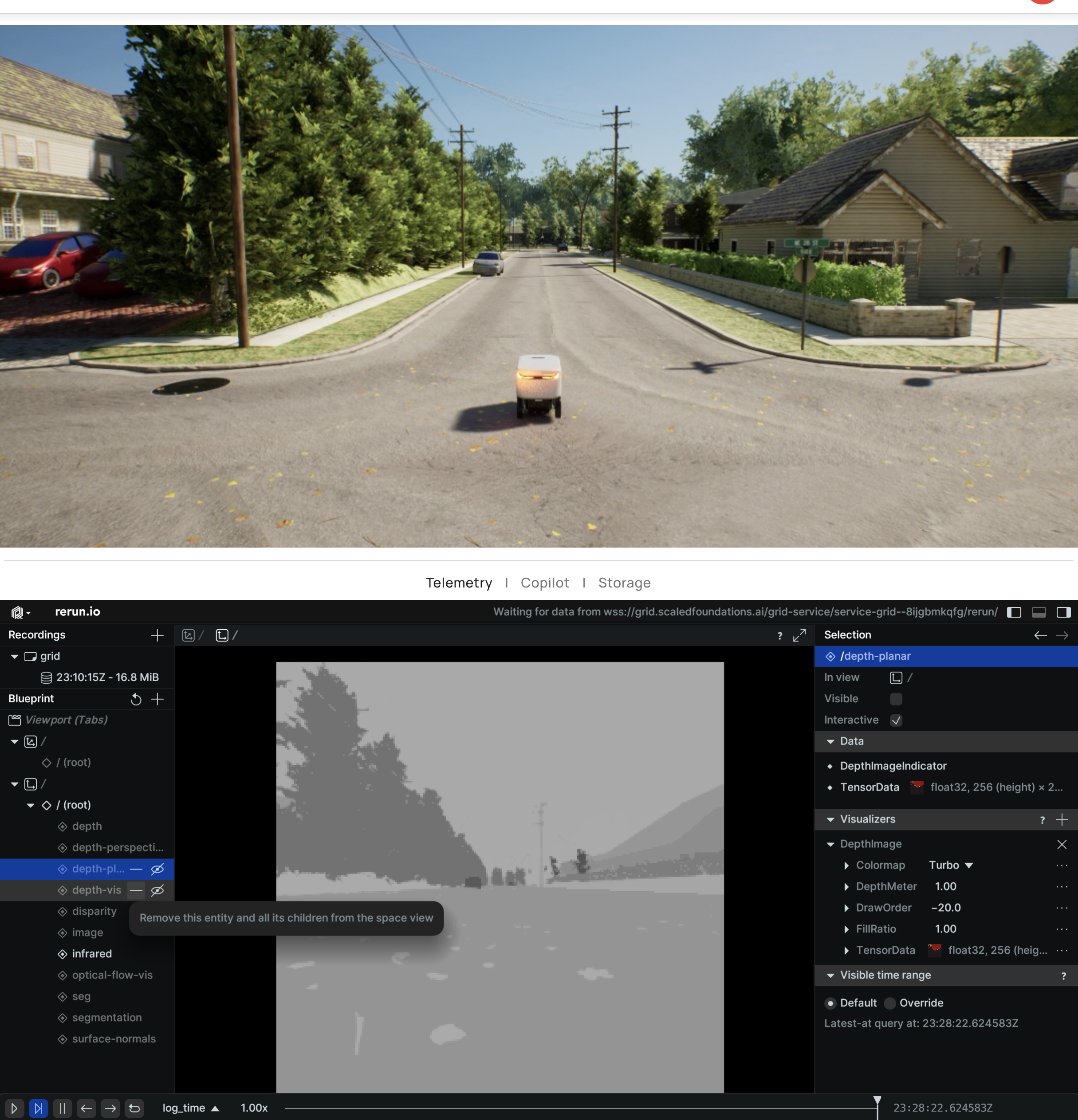
AirGen contains three types of depth sensors: *DepthPerspective*, *DepthPlanar*, and *DepthVis*.
* *DepthPerspective* is a depth sensor that uses a perspective projection model. In this image, each pixel represents the depth from the camera position using a projection ray that hits the object corresponding to that pixel.
* *DepthPlanar* is a depth sensor that returns depths in the camera plane, i.e., all points that are plane-parallel to the camera have same depth.
* *DepthVis* is a depth sensor that returns a depth image that is visualized as a B/W image. In this case, each pixel value is interpolated from black to white depending on depth in camera plane in meters. The pixels with pure white means depth of 100m or more while pure black means depth of 0 meters.
*DepthPerspective* and *DepthPlanar* return floating point images, whereas *DepthVis* is a `uint8` image in the range **0-255**.
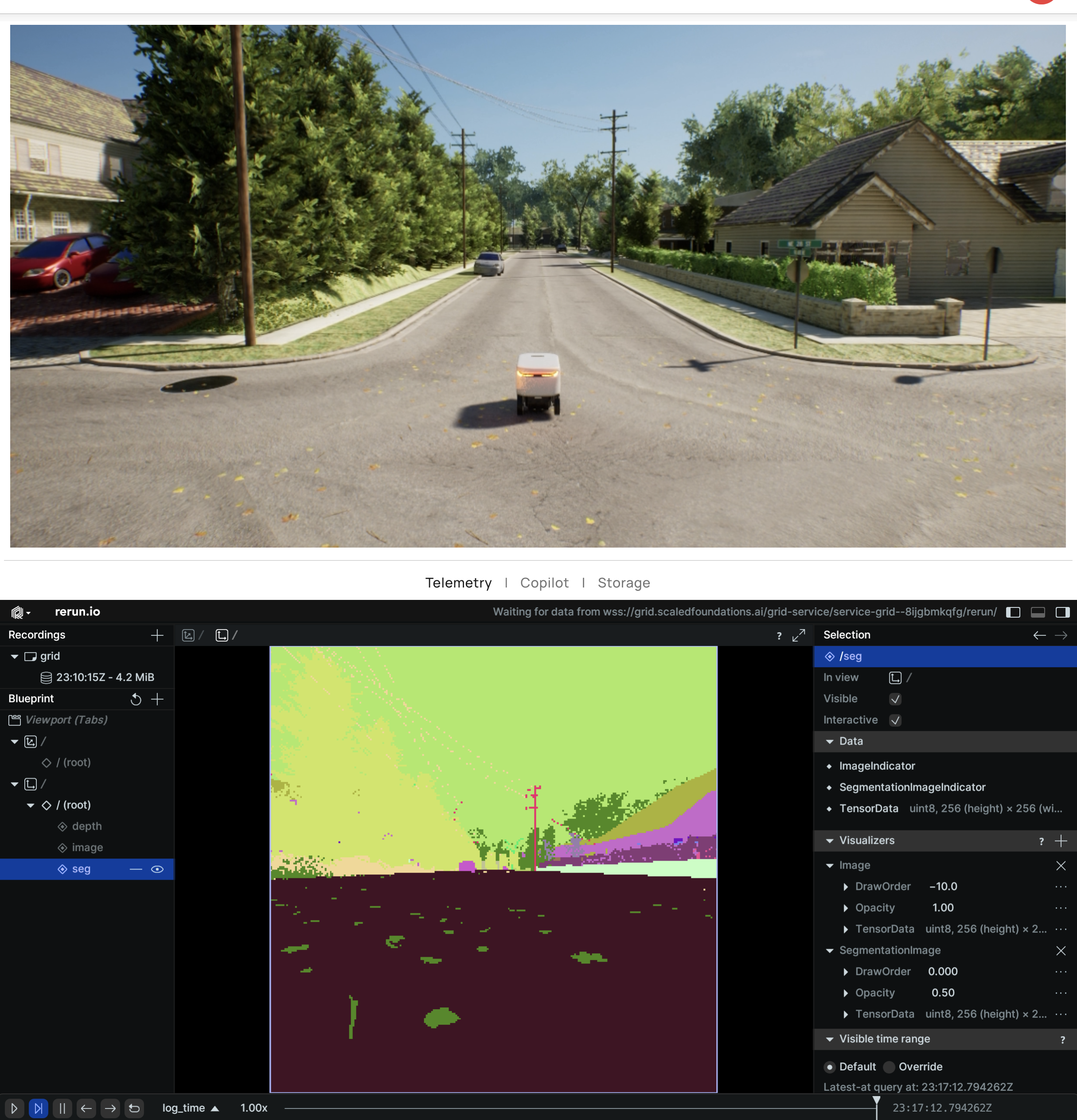
### Segmentation
The segmentation camera returns image representations of ground truth segmentation of the scene. At the startup, AirGen assigns value 0 to 255 to each mesh available in the environment. This value is then mapped to a specific color in a predefined color palette. Given which meshes are visible from the camera, the camera returns an image containing the masks with the corresponding colors.
## Camera Control
AirGen provides methods for controlling camera settings within the simulation environment, including camera pose and field of view (FOV). Below are the key methods for camera manipulation.
### simSetCameraPose
***
This function sets the pose (position and orientation) of a specified camera. You can control both internal and external cameras.
```python theme={null}
def simSetCameraPose(self, camera_name, pose, robot_name="", external=False):
"""
Set the pose of a camera.
Args:
camera_name (str): Name of the camera
pose (Pose): Desired position and orientation
robot_name (str, optional): Associated robot name
external (bool, optional): Controls an external camera
"""
self.client.call("simSetCameraPose", str(camera_name), pose, robot_name, external)
```
**Example:**
To set the pose of the `front_center` camera using AirGenCar:
```python theme={null}
import airgen
import time
import math
from grid.robot.airgen_car import AirGenCar
airgen_car_0 = AirGenCar()
client = airgen_car_0.client
def euler_to_quaternion(pitch, roll, yaw):
# Convert Euler angles to quaternion
pitch, roll, yaw = map(math.radians, [pitch, roll, yaw])
cy, sy = math.cos(yaw * 0.5), math.sin(yaw * 0.5)
cr, sr = math.cos(roll * 0.5), math.sin(roll * 0.5)
cp, sp = math.cos(pitch * 0.5), math.sin(pitch * 0.5)
return airgen.Quaternionr(cy * cr * cp + sy * sr * sp, cy * sr * cp - sy * cr * sp, cy * cr * sp + sy * sr * cp, sy * cr * cp - cy * sr * sp)
initial_pose = client.simGetCameraInfo("front_center").pose
test_poses = [
airgen.Pose(airgen.Vector3r(0, 0, -10), euler_to_quaternion(0, 0, 0)),
airgen.Pose(airgen.Vector3r(0, 0, -10), euler_to_quaternion(0, 0, 90)),
]
for pose in test_poses:
client.simSetCameraPose("front_center", pose)
time.sleep(2)
client.simSetCameraPose("front_center", initial_pose)
```
**Arguments:**
* **camera\_name:** Name of the camera
* **pose:** Pose object representing position and orientation
* **robot\_name:** (Optional) Robot to which the camera is attached
* **external:** (Optional) Controls external cameras
**Notes:**
* The Pose object follows the North-East-Down (NED) coordinate system.
* This method supports external camera control using the external flag.
### simSetCameraFov
Modifies the field of view (FOV) of a selected camera.
```python theme={null}
def simSetCameraFov(self, camera_name, fov_degrees, robot_name="", external=False):
"""
Set the FOV of a camera.
Args:
camera_name (str): Name of the camera
fov_degrees (float): FOV in degrees
robot_name (str, optional): Associated robot name
external (bool, optional): Controls an external camera
"""
self.client.call("simSetCameraFov", str(camera_name), fov_degrees, robot_name, external)
```
**Example:**
Set the FOV for the `front_center` camera to 90 degrees:
```python theme={null}
client.simSetCameraFov("front_center", 90.0)
```
**Arguments:**
* **camera\_name:** Name of the camera
* **fov\_degrees:** FOV in degrees
* **robot\_name:** (Optional) Associated robot name
* **external:** (Optional) Controls external cameras
### Coordinate System and Frame of Reference
Camera position and orientation follow the North-East-Down (NED) frame:
* **X:** Points forward (north)
* **Y:** Points right (east)
* **Z:** Points downward
Please ensure your poses are aligned with this frame.
## Further Reading
### Depth
AirGen contains three types of depth sensors: *DepthPerspective*, *DepthPlanar*, and *DepthVis*.
* *DepthPerspective* is a depth sensor that uses a perspective projection model. In this image, each pixel represents the depth from the camera position using a projection ray that hits the object corresponding to that pixel.
* *DepthPlanar* is a depth sensor that returns depths in the camera plane, i.e., all points that are plane-parallel to the camera have same depth.
* *DepthVis* is a depth sensor that returns a depth image that is visualized as a B/W image. In this case, each pixel value is interpolated from black to white depending on depth in camera plane in meters. The pixels with pure white means depth of 100m or more while pure black means depth of 0 meters.
*DepthPerspective* and *DepthPlanar* return floating point images, whereas *DepthVis* is a `uint8` image in the range **0-255**.
### Segmentation
The segmentation camera returns image representations of ground truth segmentation of the scene. At the startup, AirGen assigns value 0 to 255 to each mesh available in the environment. This value is then mapped to a specific color in a predefined color palette. Given which meshes are visible from the camera, the camera returns an image containing the masks with the corresponding colors.
 #### Assigning segmentation IDs
By default, AirGen assigns a unique ID to each mesh in the environment. However, you can assign your own IDs to the meshes using the *simSetSegmentationObjectID* method. This method takes the mesh name and the ID as arguments. The following code snippet demonstrates how to assign a custom ID to a mesh:
```python theme={null}
simSetSegmentationObjectID("chair0", 20, True)
```
Environments often contain many meshes that are of the same object type. For example, a room may contain many chairs, and a factory may contain many machines. In such cases, it is useful to assign the same ID to all the meshes of the same type. AirGen supports regex based ID assignment. The following code snippet demonstrates how to assign the same ID to all the meshes of the same type:
```python theme={null}
simSetSegmentationObjectID("chair[\w]*", 20, True)
```
An object's ID can be set to -1 to make it not show up on the segmentation image.
### Infrared / Thermal
AirGen includes an infrared/thermal camera view which simulates a non-radiometric thermal camera. Under the hood, the infrared camera view uses a similar principle as the segmentation view, but instead of using the color palette to map mesh IDs to colors, it uses a grayscale palette to map objects to grayscale values which can be thought of as relative temperatures. The infrared camera view is useful for visualizing the temperature distribution of the objects in the view, and can be used to identify hotspots and cold spots in the scene.
Users can use the *simSetSegmentationObjectID* function to assign a unique pixel value to the objects they want to visualize in the infrared camera view. The pixel value is then mapped to a grayscale value in the infrared camera view. For example, the following code assigns the highest pixel value to the object with the name Fire (assuming an object name starting with 'Fire' exists in the scene), and then captures an infrared image
```python theme={null}
client = airgen.MultirotorClient()
client.simSetSegmentationObjectID("Fire[\w]*", 255)
thermal_image = client.getImages("front_center", [airgen.ImageType.Infrared])[0][0]
```
It is important to note that the infrared camera view is not a true thermal camera, and the grayscale values do not correspond to actual temperatures.
#### Assigning segmentation IDs
By default, AirGen assigns a unique ID to each mesh in the environment. However, you can assign your own IDs to the meshes using the *simSetSegmentationObjectID* method. This method takes the mesh name and the ID as arguments. The following code snippet demonstrates how to assign a custom ID to a mesh:
```python theme={null}
simSetSegmentationObjectID("chair0", 20, True)
```
Environments often contain many meshes that are of the same object type. For example, a room may contain many chairs, and a factory may contain many machines. In such cases, it is useful to assign the same ID to all the meshes of the same type. AirGen supports regex based ID assignment. The following code snippet demonstrates how to assign the same ID to all the meshes of the same type:
```python theme={null}
simSetSegmentationObjectID("chair[\w]*", 20, True)
```
An object's ID can be set to -1 to make it not show up on the segmentation image.
### Infrared / Thermal
AirGen includes an infrared/thermal camera view which simulates a non-radiometric thermal camera. Under the hood, the infrared camera view uses a similar principle as the segmentation view, but instead of using the color palette to map mesh IDs to colors, it uses a grayscale palette to map objects to grayscale values which can be thought of as relative temperatures. The infrared camera view is useful for visualizing the temperature distribution of the objects in the view, and can be used to identify hotspots and cold spots in the scene.
Users can use the *simSetSegmentationObjectID* function to assign a unique pixel value to the objects they want to visualize in the infrared camera view. The pixel value is then mapped to a grayscale value in the infrared camera view. For example, the following code assigns the highest pixel value to the object with the name Fire (assuming an object name starting with 'Fire' exists in the scene), and then captures an infrared image
```python theme={null}
client = airgen.MultirotorClient()
client.simSetSegmentationObjectID("Fire[\w]*", 255)
thermal_image = client.getImages("front_center", [airgen.ImageType.Infrared])[0][0]
```
It is important to note that the infrared camera view is not a true thermal camera, and the grayscale values do not correspond to actual temperatures.
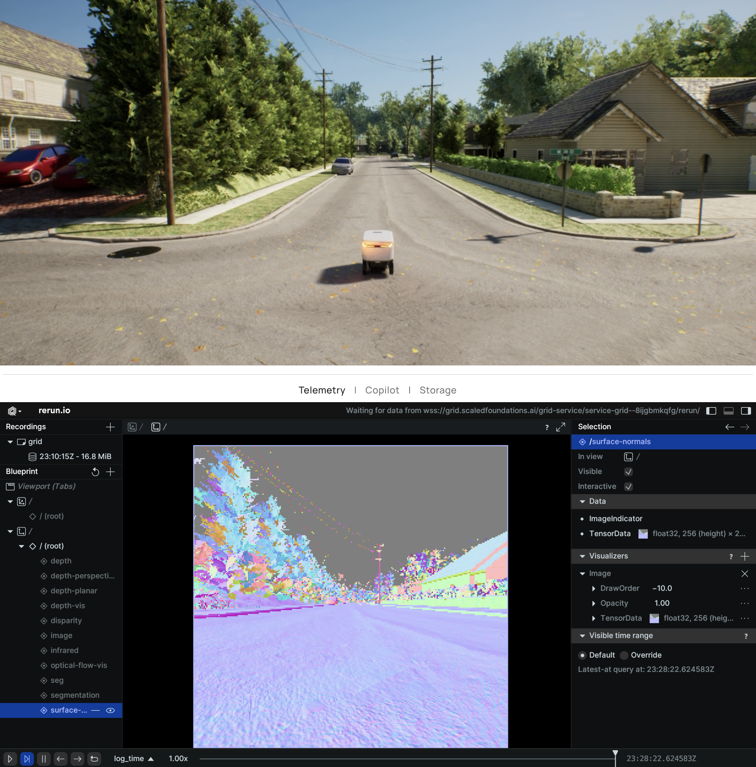
 ### Surface Normals
The surface normals camera is a view that renders the ground truth surface normals of the objects visible in the field of view as RGB colors. This is useful for viewpoint estimation, path planning and other tasks that require the 3D geometry of the scene.
Because the normal vectors at any pixel are 3D vectors with components in the range of \[-1, 1], they are encoded as RGB colors by simply scaling and shifting the components to the range of \[0, 255]. The normal vector (0, 0, 1) is encoded as the color (128, 128, 255), the normal vector (0, 0, -1) is encoded as the color (128, 128, 0), and so on. The encoding is represented as:
```
r = round(0.5x + 0.5) * 255
g = round(0.5y + 0.5) * 255
b = round(0.5z + 0.5) * 255
```
And hence, to obtain the true normal vectors from the RGB colors, the following decoding should be used:
```
x = (r / 255.0) * 2 - 1
y = (g / 255.0) * 2 - 1
z = (b / 255.0) * 2 - 1
```
### Surface Normals
The surface normals camera is a view that renders the ground truth surface normals of the objects visible in the field of view as RGB colors. This is useful for viewpoint estimation, path planning and other tasks that require the 3D geometry of the scene.
Because the normal vectors at any pixel are 3D vectors with components in the range of \[-1, 1], they are encoded as RGB colors by simply scaling and shifting the components to the range of \[0, 255]. The normal vector (0, 0, 1) is encoded as the color (128, 128, 255), the normal vector (0, 0, -1) is encoded as the color (128, 128, 0), and so on. The encoding is represented as:
```
r = round(0.5x + 0.5) * 255
g = round(0.5y + 0.5) * 255
b = round(0.5z + 0.5) * 255
```
And hence, to obtain the true normal vectors from the RGB colors, the following decoding should be used:
```
x = (r / 255.0) * 2 - 1
y = (g / 255.0) * 2 - 1
z = (b / 255.0) * 2 - 1
```
 ### Optical Flow
Optical flow is the pattern of apparent motion of image objects between two consecutive frames caused by the movement of object or camera. It is 2D vector field where each vector is a displacement vector showing the movement of points from first frame to second. AirGen's optical flow camera outputs a 2D image with the channels corresponding to X and Y components of the pixel motion.
There are two optical flow cameras available in AirGen.
* *OpticalFlow* is the raw optical flow camera which outputs the 2-channel vector field as described above.
* *OpticalFlowVis* is a 3-channel image which visualizes the optical flow as an RGB image. The color of the pixels corresponds to the direction of the motion. This view is useful for debugging and visualization purposes but should not be used as an estimation of the motion.
### Object Detection
This feature lets you generate object detection labels using the RGB camera in AirGen. To start with, you can set which object(s) should be detected and returned by this feature by name and radius from the camera. One can control these settings for each camera, image type, and robot combination separately. The output of this feature is a list of detected objects with their bounding boxes and 3D bounding boxes.
### API
Set mesh name to detect:
```python theme={null}
client.simAddDetectionFilterMeshName(camera_name, image_type, mesh_name, robot_name='')
```
Clear all mesh names previously added:
```python theme={null}
client.simClearDetectionMeshNames(camera_name, image_type, robot_name='')
```
Set detection radius in cm:
```python theme={null}
client.simSetDetectionFilterRadius(camera_name, image_type, radius_cm, robot_name='')
```
Get detections:
```python theme={null}
client.simGetDetections(camera_name, image_type, robot_name='')
```
The return value of *simGetDetections* is a *DetectionInfo* array.
```
DetectionInfo:
name = ''
geo_point = GeoPoint()
box2D = Box2D()
box3D = Box3D()
relative_pose = Pose()
```
### Optical Flow
Optical flow is the pattern of apparent motion of image objects between two consecutive frames caused by the movement of object or camera. It is 2D vector field where each vector is a displacement vector showing the movement of points from first frame to second. AirGen's optical flow camera outputs a 2D image with the channels corresponding to X and Y components of the pixel motion.
There are two optical flow cameras available in AirGen.
* *OpticalFlow* is the raw optical flow camera which outputs the 2-channel vector field as described above.
* *OpticalFlowVis* is a 3-channel image which visualizes the optical flow as an RGB image. The color of the pixels corresponds to the direction of the motion. This view is useful for debugging and visualization purposes but should not be used as an estimation of the motion.
### Object Detection
This feature lets you generate object detection labels using the RGB camera in AirGen. To start with, you can set which object(s) should be detected and returned by this feature by name and radius from the camera. One can control these settings for each camera, image type, and robot combination separately. The output of this feature is a list of detected objects with their bounding boxes and 3D bounding boxes.
### API
Set mesh name to detect:
```python theme={null}
client.simAddDetectionFilterMeshName(camera_name, image_type, mesh_name, robot_name='')
```
Clear all mesh names previously added:
```python theme={null}
client.simClearDetectionMeshNames(camera_name, image_type, robot_name='')
```
Set detection radius in cm:
```python theme={null}
client.simSetDetectionFilterRadius(camera_name, image_type, radius_cm, robot_name='')
```
Get detections:
```python theme={null}
client.simGetDetections(camera_name, image_type, robot_name='')
```
The return value of *simGetDetections* is a *DetectionInfo* array.
```
DetectionInfo:
name = ''
geo_point = GeoPoint()
box2D = Box2D()
box3D = Box3D()
relative_pose = Pose()
```