> ## Documentation Index
> Fetch the complete documentation index at: https://docs.generalrobotics.dev/llms.txt
> Use this file to discover all available pages before exploring further.
# Camera Calibration
> Extrinsic camera calibration for a robot arm
## Overview
This is a guide on how to use the camera calibration repository `git@github.com:GenRobo/camera_calibration.git` to do an extrinsic camera calibration for robot arms.
## Step 1: Create a Calibration Target
Generate a Radon Checkerboard pattern using the `gen_pattern.py` script. For example:
```bash theme={null}
python pattern/gen_pattern.py -o radon_checkerboard_12x9_19mm.svg --rows 12 --columns 9 --type radon_checkerboard -s 19.0 -m 4 6 4 7 5 6
```
Print the svg file on paper and attach it to a rigid flat board. Make sure of the following:
* There is a white border of at least one square-width on all sides of the pattern
* The pattern is unobscured and has no creases or unevenness
* Measure the square side-lengths to make sure they are to scale
If you want to do a "Hand-in-eye" calibration, then attach the board to your robot's end-effector, and the camera should be fixed with respect to the robot base.
If you want to do a "Eye-in-hand" calibration, then attach the board at a fixed location with respect to the robot base, and the camera should be mounted on the robot's end-effector.
It is possible to attach the board using tape, but it is recommended to use a more rigid method like a 3D-printed mount. The board and camera should never wiggle during the calibration process!
## Step 2: Calibrate the Camera
You will have to write a script that provides all of the necessary information to the `extrinsic_calibration_interactive()` function. The `examples/` directory shows how to do this in various configurations of robots and cameras. These examples automatically run interactive data collection and calibration:
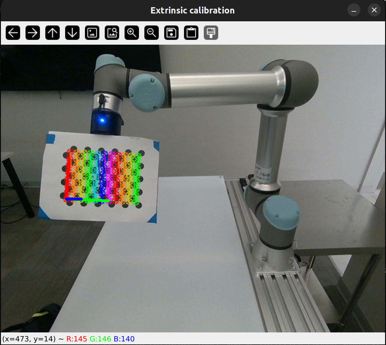
Data collection: When you start the script, a video feed will be shown with the detected calibration target. You need to free-drive the robot to different positions and orientations. Press \[Spacebar] to collect a sample and \[c] to move on to calibration (once you have collected enough samples).
Each "sample" consists of the robot's end-effector pose (from inverse kinematics) and the detected points of the calibration target in the camera's image. For a good calibration, you need to get a good distribution of size, skew, and location of the calibration target in the image. 10-15 samples generally gives good results, but more is better.
You should expect to see the following display and terminal output:
 ```
$ python examples/ur5e_extrinsic_calibration.py
OpenCV version: 4.11.0
Starting UR5e Extrinsic Calibration
Starting to initialize RealSense Camera
Initialized!
Robot initialized, running extrinsic calibration
Press [Spacebar] to collect a sample
Press [c] to calibrate (once you've collected enough samples)
...
Saved raw data to
Saved poses to
Collected 1 samples
```
> **FAQ**: The calibration target does not appear to be recognized in the image.
>
> **Answer**: Make sure that the target is non-reflective and has the correct number of rows and columns. This script counts the number of *squares* in the row and column count, but openCV convention is sometimes to take the number of *interior corners* (the number of points detected in the image), which is one less than the number of squares.
Calibration: Once enough samples are collected, you can press \[c] to calibrate the camera. Internally this uses the OpenCV function `calibrateHandEye`.
The output will be a csv file containing the camera's pose with respect to the desired robot link. For a Hand-in-Eye calibration this will be `camera_wrt_base.csv`, and for Eye-in-hand calibration this will be `camera_wrt_gripper.csv` (where 'wrt' means "with respect to").
You will also get a reprojection error, which tells you the pixelwise distance between the actual detected points, and the reprojection of the 3D pattern points using the transforms output by the calibration. As a rule of thumb, a "good" calibration will have a reprojection error of less than 0.15 pixels, and if the error is over 0.3 then you should re-do the calibration.
## Step 3: Visualize the Results
The `visualize_calibration.py` file also contains functions that can be used to visualize the camera's pose and end-effector pose relative to the robot base. Examples are shown in the `examples/` directory. The plot is simple, but it can show movements of the end-effector in real time.
## Tested with:
Robots:
* UR5e
* WidowX 250S
Cameras:
* Realsense D435i
* Realsense D455
* Zed 2i
```
$ python examples/ur5e_extrinsic_calibration.py
OpenCV version: 4.11.0
Starting UR5e Extrinsic Calibration
Starting to initialize RealSense Camera
Initialized!
Robot initialized, running extrinsic calibration
Press [Spacebar] to collect a sample
Press [c] to calibrate (once you've collected enough samples)
...
Saved raw data to
Saved poses to
Collected 1 samples
```
> **FAQ**: The calibration target does not appear to be recognized in the image.
>
> **Answer**: Make sure that the target is non-reflective and has the correct number of rows and columns. This script counts the number of *squares* in the row and column count, but openCV convention is sometimes to take the number of *interior corners* (the number of points detected in the image), which is one less than the number of squares.
Calibration: Once enough samples are collected, you can press \[c] to calibrate the camera. Internally this uses the OpenCV function `calibrateHandEye`.
The output will be a csv file containing the camera's pose with respect to the desired robot link. For a Hand-in-Eye calibration this will be `camera_wrt_base.csv`, and for Eye-in-hand calibration this will be `camera_wrt_gripper.csv` (where 'wrt' means "with respect to").
You will also get a reprojection error, which tells you the pixelwise distance between the actual detected points, and the reprojection of the 3D pattern points using the transforms output by the calibration. As a rule of thumb, a "good" calibration will have a reprojection error of less than 0.15 pixels, and if the error is over 0.3 then you should re-do the calibration.
## Step 3: Visualize the Results
The `visualize_calibration.py` file also contains functions that can be used to visualize the camera's pose and end-effector pose relative to the robot base. Examples are shown in the `examples/` directory. The plot is simple, but it can show movements of the end-effector in real time.
## Tested with:
Robots:
* UR5e
* WidowX 250S
Cameras:
* Realsense D435i
* Realsense D455
* Zed 2i